Blinkentree
| | |
|---|---|
| We built our own blinking X-mas tree for the market in Strassen. | |

| |
| Meetings: | none |
| Type: | hardware |
| Tracker: | https://source.hacker.lu/projects/blinkentree |
| Status: | concluded |
| Members: | |
| Contact Person: | slopjong (mail), prometheus (mail) |
| Tools | |
| QrCode: | 
|
Diese Seite gibt es hier auch in deutsch.
Contents |
Introduction
What is this flashing green fir tree about?
As creative hackers, we thought it would be necessary to support the Christmas market of the commune of Strassen with something tiny, but creative. Result? The Blinkentree. Obviously it represents a green fir tree that is dorned with flashing LEDs which should represent the baubles of a 'real' tree.
A big thanks to all of you folks who purchsed a Blinkentree and thus supporting syn2cat Hackerspace.
Hacky Christmas!
Assembling the kit
If you didn't buy a kit but an already assembled Blinkentree you can continue with the next section.
Otherwise follow the next instructions to assemble your kit. We recommend to first solder the resistors, then the chip socket and then the LEDs because it's easier to start with the small devices and finally solder the biggest ones.
- The resisostors have all the same value and they don't have any polarity so it doesn't matter what direction they're put on the board.
 Place the resistors as shown here.
- The chip socket has an indentation which must be oriented down.
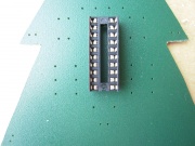 Chip direction. The indentation comes down.
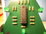 Chip direction. The indentation comes down.
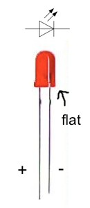
 - The LEDs have a polarity. The long leg is positive (+) and the small one is negative (-). The current flows from the positive to the negative so you have to pay attention while you assemble the kit. The LEDs are flat on the negative side. You have to orientate the LEDs as shown on the second picture (click on it to resize it).


How to program it on your own?
The goal of our Blinkentree project was to offer you a christmas tree that you can reprogram. The flashing patterns can be changed by yourself. If you never have programmed before you might think that it's getting too complex now.
This is true if you don't want to learn something new. It's not true if you want to get new skills. This howto is intended to be understood by everyone. Even by those who don't know much about programming. If you come across stuff that's too unclear for you let us know and we help you (electronics[at]hackerspace.lu).
If you're completely new to the microcontroller world there are essentially four steps to be followed.
- Get the compiler tools
- Write the program
- Compile the program
- Get the compiled program into the microcontroller
Get the compiler toolchain
Before we start writing the program we must install the compiler. A compiler is a program which reads your program text (source code) and turns it into machine code which is a series of instructions that the controller will execute later. One instruction could be "set pin 3 of port B to high". Thus you could switch on an LED.
A very common compiler is the GCC compiler which is part of the WinAVR (Windows) and CrossPack-AVR (Mac). You might already have guessed it, we are using the C language here.
Windows users download WinAVR and mac users should download CrossPack AVR instead.
If you downloaded the windows version the installer will ask you to make an entry in the PATH variable. Be sure that the checkbox in the dialog is checked.
If you downloaded the mac version the installer will put the stuff into /usr/local/CrossPack-AVR [1]. Now the compiler should be on the PATH. You can check this by opening a terminal (shell) and typing inecho $PATH
There should be /usr/local/CrossPack-AVR/bin present. If not execute this to add it:
echo -e " \n \n export PATH=/usr/local/CrossPack-AVR/bin:$PATH" >> ~/.profile
Coding
For both Windows and Mac chose a good editor like Notepad++ or Programmers Notepad for Windows and TextWrangler for Mac.
Defining new flashing patterns for your Blinkentree is easy. Here is a sample code:
#include <avr/io.h>#include <util/delay.h>int main(void) {
// configure the ports as outputsDDRD = 0b11111111;
DDRB = 0b11111111;
while(1)
{PORTB = 255;
PORTD = 0;
_delay_ms(400);
PORTB = 0;
PORTD = 255;
_delay_ms(400);
}}
Save this code in the file main.c . Brief, this program powers on and off all the LEDs by setting all output pins to HIGH (255 as value) or LOW (0 as value).
In the first two lines one library for input/output (I/O) operations and one library for delay operations are included.
In line 4 you define the main function that will be executed by the Blinkentree as soon as it's powered on.
The DDRD and DDRB variables are defined to configure the ports D and B which could be either as input or as output. DDR stands for Data Direction Register and the following letter A, B, C or D defines the port. We initialize both, DDRD and DDRB, with 0b11111111 which are binary numbers where each 1 stands for one pin of the port. 1 means that the pin is set as an output wheras a 0 would be used to configure the pin as an input.
By setting the port B to high (255 = 0b11111111) in line 12 we turn on all the LEDs of that port. If you want to turn on only certain LEDs you have to set other values from the range 0 to 255 (0b00000000 to 0b11111111). For some more advanced pin settings read this tutorial. You can use the decimal-binary converter to convert decimal numbers in binary numbers and vice versa.
The while loop is used to execute the flashing pattern repeatedly. Otherwise the microcontroller would stop at the end of the main function. In other words the flashing pattern would be executed only one time.
On Suhas's blog you find more information about the I/O operations.
The code the Blinkentree is shipped with can be found here.
Compiling and linking
When the coding is done translate it into machine code by opening your terminal (shell, command line or also known as cmd on Windows) and changing into the directory where your code file is.
There you you type in:
avr-gcc -Wall -Os -std=c99 -DF_CPU=1000000 -mmcu=attiny2313 -c main.c -o main.o
avr-gcc -Wall -Os -std=c99 -DF_CPU=1000000 -mmcu=attiny2313 -o main.elf main.o
avr-objcopy -O ihex -R .eeprom main.elf main.hex
These commands are the same for Mac and Windows. We assume that you are not (yet) interested in what those lines exactly mean so don't care about them now.
If nothing went wrong you should have main.hex which is the translated code. This will be loaded into your microcontroller in the next step.
Flashing the microcontroller
Congratulations! You're not yet bored about this stuff :-)
Now it's getting a bit tricky. You need a programmer device to upload your code to the controller. We used the USBasp programmer which you can buy here. As the USBasp programmer is an open source project you can also build it yourself.
Important: If you buy the ATMega chip somewhere else it might missing the required firmware. In this case you need another programmer to get the programmer firmware into yours so you'll probably run into the chicken-and-egg dilemma.
Mac and Linux users don't need any driver for the programmer but Windows users do. Download it here.
If you finally got a programmer you need to solder a pin header on your board. Have a look at your tree, there are six holes that are reserved for this purpose. You get such a pin header in any electronics store. In Luxembourg there are S.A.M., Secto and Schaller. Maybe there are others but these are the ones we know. In Germany Reichelt and Conrad are well-known.

The pins from left to right are:
1. MOSI | 2. MISO | 3. SCK | 4. GND | 5. VTG | 6. RST
On the USBasp you have this connector:

Connect all the pins with the same name. If you also connect VTG you have to switch off the Blinkentree and if you don't connect it you have to switch it on.
Go into your shell / command line and execute this
avrdude -c USBasp -p t2313 -U flash:w:main.hex -v -F
On a mac and probably under linux too you must execute it with sudo.
Then you have to execute
avrdude -cUSBasp -p t2313 -U lfuse:w:0x64:m -U hfuse:w:0xdf:m -U efuse:w:0xff:m
on Windoze
and
sudo avrdude -cUSBasp -p t2313 -U lfuse:w:0x64:m -U hfuse:w:0xdf:m -U efuse:w:0xff:m
on a Mac. -->
References
Footnotes
- ↑ /usr/local/CrossPack-AVR is just a symbolic link to /usr/local/CrossPack-AVR-20100115 or something like that.